|


OBSELETE Simplex Building Network interface card for 4100ES or newer(4100-6047)
Building Network interface card for 4100ES or newer(4100-6047)
SKU
4100-6047
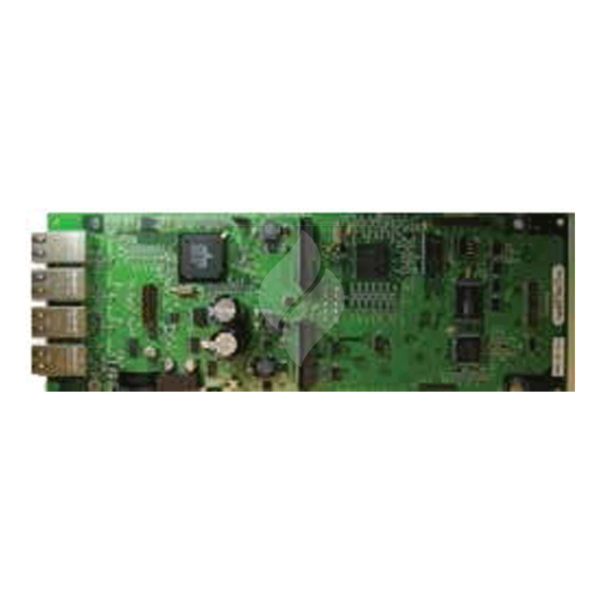
The Building Network Interface Card (BNIC) allows the connection of a 4100ES Fire Indication Panel (FIP) to a local area Ethernet network (LAN) or to a dedicated Ethernet network used only for the fire alarm systems.
The BNIC isolates the FIP from the external or building network but allows an authorised user to access the FIP through the network. Network authorisation is provided transparently through service tools such as the ES Programmer.
Dual Inline Package (DIP) Switch SW1 is used to set the BNIC eSlave address as identified in the ES Panel Programmer job. The address is set with the card in its normal orientation (connectors up) as shown in the mounting instructions.
Jumper P1 sets the Autoforward mode to determine how data traffic is handled before the BNIC CPU is online.
- Setting 1-2:
- This is the recommended default setting. In this mode the BNIC does not allow traffic to be routed through the switch until the BNIC CPU is online and running.
The BNIC must be mounted in the master controller cabinet and can be placed in any open expansion bay slot.
Note: The card must be installed with the ports facing up.
Use the following steps as well as Figure 5 to properly install the BNIC:
- Insert the Power Distribution Interface (PDI) connector on the back of the card into one of the bottom PDI connectors on the expansion bay.
- Secure the card in place using the provided hardware.
All Ethernet ports on the BNIC are auto-crossover (crossover cables are not required) and compatible with 802.3u, 100Base-TX type standard RJ45 type connections.
Cable requirements:
- Category 5 (CAT5) cable or greater is required for 100Mbit operation. Using lower grade (i.e. Category 3) cables can result in slower link speeds or shorter distances which may affect the performance of your connection.
- The maximum distance from the BNIC to the next Ethernet termination (router, switch etc.) is 328 ft (100 m) with CAT5 cable.
- Cables are to be in conformance with TIA/EIA-568-B standard.
Not supported:
- Style 7 connection. Only one path through the building network should exist. Note: Multiple connections to separate networks are permissible (i.e., dedicated network and building network).
- Power over Ethernet (PoE).
Datasheet & Specifications
| Card Size: | 4 x 11¼ inches (102 x 286 mm) /Dual Block Module |
| Earth Fault Detection (Port A only): | 10 K Ohm Max direct current connection to earth |
| Operating Temperature Range: | 32oF - 120oF (0oC-49oC ) |
| Operating Humidity Range: | Up to 93% relative humidity at 90oF (32oC ) |
| Operating Voltage: | Nominal 24 VDC from PDI |
| Maximum Current over Operating Range: | 291 mA (maximum over range) |
![]() Simplex Ethernet Module Building Network Interface Card 4100-6047 Datasheet
Simplex Ethernet Module Building Network Interface Card 4100-6047 Datasheet
Note: The BNIC is for ancillary use only and does not provide any fire alarm or burglary function other than a tool for service technicians to use in configuring and maintaining the system.