|

Room Integrity Testing
Service
Enclosure Integrity Testing
Equipment
Retrotec Room Integrity Testing
Testing
Annual Enclosure Integrity Test
Why Room Integrity Matters
Maintaining the Protected Enclosure
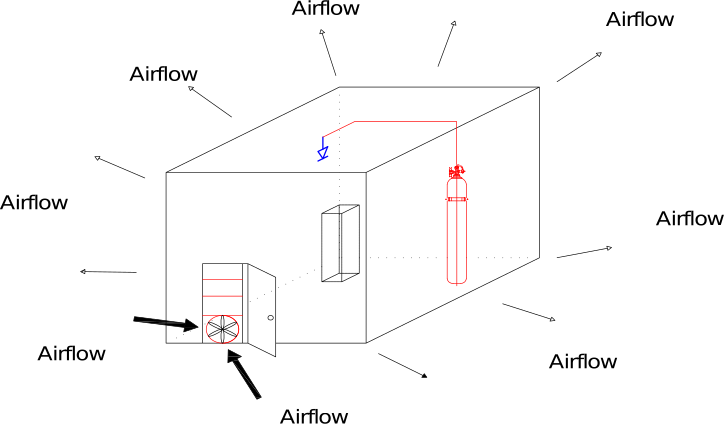
Rooms can become leakier over time, commonly due to changes in construction, cabling or services. Maintaining good room integrity is therefore important to the performance of a gas suppression system.
Gas suppression systems are a logical fire suppression solution for rooms containing I.T. or electronic equipment. These rooms can also be heavily modified as power, connectivity and cooling requirements change over time.
If a room leaks, the fire suppression agent can escape before the fire is controlled effectively.
Protected Areas
A Room Can Change After the System is Installed
Changes to cabling, services, construction and cooling requirements can alter the integrity of the enclosure. Room Integrity Testing provides information about the condition of that protected space.
NSW Fire Safety Requirements
AS 1851-2012 in NSW
AS 1851-2012 sets requirements for the routine servicing of fire protection systems and equipment. From 13 February 2026, the Standard is mandatory in NSW under the Environmental Planning and Assessment (Development Certification and Fire Safety) Regulation 2021.
01
Mandatory From 13 February 2026
NSW Government states that AS 1851-2012 became mandatory in NSW from 13 February 2026.
02
New & Existing Buildings
The NSW requirements apply to new and existing Class 1b and Class 2 through to Class 9 buildings.
03
Building Owner Responsibility
Building owners are responsible for ensuring essential fire safety services are maintained in accordance with AS 1851-2012.
The existing FSP Room Integrity Testing information identifies the Enclosure Integrity Test as an annual requirement under AS 1851-2012.
FSP Testing Capability
Trained & Accredited Retrotec Operators
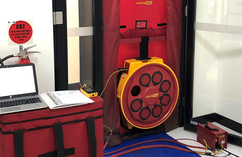
Fire Systems Products technicians are trained and accredited operators of Retrotec Room Integrity Testing equipment.
FSP uses Room Integrity Testing equipment to provide information about the integrity of the protected area and the leakage that may exist within the enclosure.
Testing of gaseous protected rooms can be arranged at convenient times to minimise disruption to your business.
The Testing Method
What is a Door Fan Test?
The door fan measures the enclosure leakage area and the pressures that may exist across the enclosure.
Together with the DG-700 Hand Held digital pressure I-flow gauge, computer software performs the simulation and produces the prediction. Retrotec CA2001 software guides the operator through the testing steps according to the applicable standard.
The Testing Process
How Room Integrity Testing Works
The door fan creates a pressure difference across the enclosure. The airflow required to create that pressure is then used to calculate the leakage area of the room.
01
Install the Fan
The Minneapolis Fan Test Unit is temporarily installed in a doorway leading from the protected space to a large open area or outdoors.
02
Create Pressure
Fan speed is adjusted to create a pressure difference between the test room and the surrounding volume.
03
Measure Airflow
The airflow required to create the pressure difference is measured during the test.
04
Calculate Leakage
Airflow and pressure measurements are used by the software to calculate the Equivalent Leakage Area of the enclosure.
05
Predict Retention
Test measurements and room information are used by the model to predict retention performance.
Measuring Room Leakage
Measuring the Enclosure
The Minneapolis Fan Test Unit is adjusted to create pressure between the room and its surrounding area. The existing FSP testing procedure describes this as usually between 10 and 15 Pa, or 0.04” to 0.06” W.C.
This pressure is similar to the steady-state pressure exerted by the gaseous extinguishing agent at floor level at the start of a typical 10 minute retention period.
Leakage Measurement
Equivalent Leakage Area
By measuring airflow rate and the pressure created, the computer software calculates the Equivalent Leakage Area. This represents the total area of cracks, gaps and holes in the test room.
Leak Identification
Finding Leakage Points
The pressure created by the fan causes air to move through leaks at a detectable rate. Chemical smoke can then be used to help pinpoint where those leaks occur.
Measurement 01
Depressurisation
The first measurement is taken by blowing air out of the room.
Measurement 02
Pressurisation
The second measurement is taken by blowing air into the room. The two readings are then averaged.
Improving Measurement Accuracy
Why the Two Readings are Averaged
Pressurisation and depressurisation readings are averaged to reduce errors caused by factors identified in the existing FSP testing procedure.
- HVAC operation can significantly affect the measurement and can produce errors of 30%.
- Other static pressures can affect results. Wind can create errors when the room gauge is fluctuating, with 5 Pa of fluctuation noted as capable of producing a 30% error.
- One-way leaks are almost never a factor in how retention time is calculated.
Retention Prediction
How the Agent Behaves in the Protected Room
The gaseous extinguishing agent mixes upon discharge, producing a homogeneous mixture. The Room Integrity Testing model then considers how the agent behaves during the retention period.
Case 01
Descending Interface Case
If air-moving equipment in the room is shut off at discharge, the agent mixture tends to remain separate from the air entering through upper leaks.
The intersection between the agent mixture and the clean air above is referred to as the agent/air interface.
The interface drops as agent is lost through leaks in the floor and lower wall area, while outside air generally enters through leaks higher in the room.
Case 02
Continual Mixing Case
If air-moving equipment remains operating during the retention period, infiltrating air becomes mixed with the extinguishing agent.
In this case the concentration at floor level decays at the same rate as the concentration near the ceiling.
Other airflow, including damper or duct leakage, can produce static pressure that pushes the agent out faster. The existing procedure notes that this static pressure is usually eliminated.
Room Measurements
Leakage Area, Pressure & Room Variables
The door fan measures total leakage areas and static pressures.
Below-ceiling leaks can be measured separately using a flex duct or plastic on the ceiling to neutralise ceiling leaks.
Other variables, including room volume and heights, are measured on site and used by the prediction model.
Retention Prediction
Predicting Retention Time
The model predicts how many minutes it will take for the descending interface to reach the minimum protected height specified by the Authority Having Jurisdiction, or for concentration to fall to the minimum acceptable percentage in the continual mixing case.
Test Relationship
How the Door Fan Test Relates to a Discharge Test
For the descending interface case, the minimum protected height is usually selected at the same location where the highest acceptance sampling probe would be located.
The less common continual mixing case is equivalent to the minimum allowable design concentration.
Room Integrity Testing
Supporting Protection & Reliability
The purpose of Room Integrity Testing and the associated survey is to provide property managers and owners with information about the level of protection and reliability of each protected hazard area.
Fire protection systems and equipment also need to be properly managed and maintained to support their performance and reliability when required.
Arrange Room Integrity Testing
Contact Fire Systems Products to discuss your Room Integrity Testing requirements.